Hello, neon•Volt.
neon.Volt? What?#
It’s a smart power supply that runs off of USB-C, utilises the rev 2 power delivery spec and is configurable over UART, but also comes with a physical UI so it’s usable as a standalone unit. It is my intent to share this design, so I will probably put it out there under GPL or something. At the time of me writing this, i’m still in the middle of finalizing the system design, but I have enough stuff on there that the code for this project is going to keep me busy for a while - even if I vibe code parts of it. Especially if i vibe code it. The short spec sheet is as follows: 100W, 98.5% efficient, 10mV adjustment steps, controllable via UART. The reality of the situation though, is that I will not be able to guarantee that efficiency and the converter will probably not be that precise, especially with cheap leads and high currents. I can’t foresee everything that will go wrong with it. There’s been feature creep. What started out with me adding hardware to meet the system specification ended up being “hey, if i’m doing this anyway, I might as well do more of the same” and that’s how I arrived at a full 16 bit user addressable terminal block, a user accessible ADC pin, a dedicated 3V3 rail and an adjustable output of 1 to 30 volts, a color 320x240 screen and enough flash memory to comfortably run Doom on this thing.
Why though?#
So I was at my new job and as many engineers probably know, you don’t get to do much in
your first few weeks. Onboarding slides, some compliance PDFs, etc. I was supposed to be catching up on the ongoing projects and stuff, but I was often
waiting on system access or just other people. This had me thinking of maybe picking up a project
to work on so my skills don’t atrophy and my pick ended up being a SCARA design from a few years back,
hoping to improve on it, maybe play around with some FOC and precision BLDC control. I did this
on the side as I was moving house - the new job was a 2.5 hour train ride away, which does not
make for a fun commute. I couldn’t bring any of my gear early on as during my mandatory period, I lived in hostels and AirBnB-s. For 4 months. This is not favorable to lab type of work,
The worst was that out of all the things, I lacked a portable.
power source. This lit a lightbulb in my head - why not just.. make one? I lack practice in power electronics so I could get hands on experience. I can customise it. I can play with the USB-C power delivery specification.
As is often the case, I dove headfirst into the more fun parts like selecting the switcher, drawing the transfer functions onto a Bode plot etc, but I figured, before I commit too much of my time to this, I should at least CHECK
what’s on the market fist. The results were not inspiring. I dislike the toaster looking devices because they’re bulky, dumb and don’t do USB.
There’s the two USB based chinese units, FNIRSI DPS-150 (really rolls off the tongue, that one) and AlienTek DP100.
There’s also the pocketPD project: https://hackaday.io/project/194295-pocketpd-usb-c-portable-bench-power-supply.
Functionally, the main issue I have with all of them is that they don’t go over 20V on USB and they don’t go low enough either.
The chinese units start at 5V while the pocketPD starts at 3V3. This is good for a lot of hobbyist stuff, so for many people, these will be okay, but the pocketPD in particular irks me. It has no switcher and as such it has none of the expensive parts, they’re also making them in China and they’re still charging $60 per unit. The idea is there though - a type C power brick already has a switcher, so why add another one.
Well, I’m making a smart power supply here. I need it to put out volts, yes, but also I want to program custom sweeps, ADC or GPIO triggered voltage/current switches, etc. This is not something you can get from any of these units. Sure, I could buy a Keithley or a R&S, but I like having both of my kidneys. And then there’s the issue of playing Doom on it. No Keithley runs Doom and dammit this is important.
So that’s where we’re at today. With any luck, I’ll finish the system design before the end of August, but I wanted a first post up just to have any kind of urgency with it, because without that, I will not finish this in the near future.
System architecture#
The system electronics are broken into 3 logical units:
IO - everything that faces the outside world.
Power - the DC-DC stuff.
MCU - MCU and system-side IO enhancements (mux, GPIO expander).
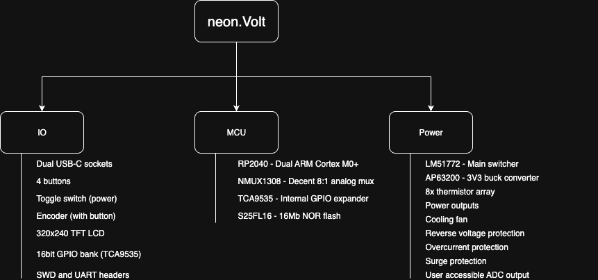
MCU#
This is the most boring block here to be honest, it’s just the RP2040 alongside its’ life support. I ran out of GPIO before half the system design was done so I added a GPIO expander. This is currently sitting at 8 free pins so the system has room to expand still, but I’ve already added everythig to it that I could think of. At least everything that’s useful. The 8:1 mux is also not strictly necessary, I can probably get away with a 4:1 and this frees up an additional control pin or I could move the control pins to the expander.
IO#
This block has two USB-C ports, one for power and one for programming. There is technically no need to separate them, but data sources generally don’t do 100W and talking to the device through a power brick is also rather difficult. The PD controller is an STUSB4500. I went with this over the chinese offerings (CH224, HUSB238) because it offers more control and adds a layer of safety. Then there’s the cherry mx style switches and keycaps, an EC11X encoder an ILI9341 SPI screen and a user addressable 16-bit GPIO bank that’s programmed via I2C. The idea is to abstract the I2C from the user and implement a kind of interpreter that you can invoke via UART or load a script from flash. I haven’t given this much thought though, but the easiest way to get this off the ground is to simply give the MCU an I2C mode via the UART interface that takes input in the form of pin_nr/pin_direction/set_state/get_state. For this to actually be useful, automatic control is a must. This GPIO bank is technically pretty capable, each pin can source 25mA of current and if you can tolerate the I2C speeds (400kHz), you can do anything with this that you would normally need a separate MCU for. This is a rev a feature, just throwing stuff at it and seeing what sticks. I don’t know how much I would actually use this. The exposed ADC pin is a bit more useful though. It can serve as a makeshift DMM in a pinch and it’s buffered so it’s easier to use than throwing together some impromptu garbage on a breadboard. It’s definitely faster to get going with this too.
Power system#
…is designed for monkeys with breadboards. The outputs are standard 4mm banana plugs and they have pretty robust protections. The main output has an LM5050 driving two back to back N-channel mosfets, followed by a PESD30 device in a DO214 package. This should take care of transients, inductive incidents (direct motor drive) and reverse voltage. These mosfets are also the last line of defense for overcurrent as when these burn, the circuit fails open and it stops working, the switcher and the rest of the system remains intact. Actual overcurrent protection is implemented on 3 levels. The input STUSB4500 has a hard current limit that it negotiates and this is calculated on the fly for all output voltage levels. The LM51772 itself has a hard current limit that’s programmable via I2C and similar math is used here to adjust it on the fly. On top of that, I have shunt resistors monitored by the MCU to determine current in realtime. This amount of redundancy is pretty normal for a device like this imo, but this is also a revision a board so I’m throwing everything at it and run extensive tests when I finally have one of these assembled. The outputs are bolted to the PCB using M3 bolts, the annular rings of these are oversized and peppered with vias.
Current progress#
I’m done with the following:
Math
Schematics
Preliminary BOM (inc chassis and fan)
Preliminary outline with button and LCD placement
Board stackup
I’ve written some of the firmware and am contemplating life choices, because I think I need to do this in C++, for the UI at least. A menu driven system fits OOP pretty well, in ye olde C it’s going to be a clusterfuck of a state machine with a thousand+ lines of code. I’m about to start doing the layout. It’s a bit of a problem because layout requires 2 monitors and I’m rarely in the mood to sit at my desk when I’m at home, I’ve done the bulk of the work on this project spread out on a chouch or on the train.
One last thing though. The f is a neon.Golem?#
Ah, yeah. Welcome. I’m pretty big on the whole cyberpunk aesthetic, so that’s neon. I play with robots, so Golem - an automaton from the jewish mythos. It’s a project portfolio and a way for me to vent when I want to scream, but don’t want to piss off my friends.